Pitch and Lead: The Two Most Commonly Confused Parameters
Before setting up thread programs or selecting tools, two parameters with similar definitions but completely different practical meanings must be clarified.
Pitch (P)
The axial distance between adjacent thread crests, represented by P, typically in millimeters. The most commonly dimensioned specification on drawings and the direct basis for insert selection and program setting.
Lead (L)
The actual axial distance traveled by a nut or bolt after the thread completes exactly one full revolution. For single-start threads, lead equals pitch; for multi-start threads, the two values differ significantly.
Single-start (n=1): L = P
Double-start (n=2): L = 2P
Multi-start threads are common in mechanisms requiring fast linear displacement — such as camera lens focus rings, bottle caps, and machine tool ball screws — where increasing the number of starts raises per-revolution travel without reducing the pitch.
Single-start thread: lead = pitch; simply enter the pitch value.
Multi-start thread: enter pitch × number of starts, and use start-angle phase offset (Indexing) to cut each start separately.
For example, with a double-start thread M20×P2.0: the F value should be entered as 4.0mm (2.0 × 2), and two start positions (0° and 180°) must be set via Q command or phase offset to correctly cut both starts. If only the F value is increased without addressing the start-angle phase, the result will be a single helical groove rather than a double-start thread — the most common mistake in multi-start thread programming.
Metric Coarse Thread Common Specifications
| Nominal Diameter (D) | Standard Pitch (P) | Recommended Tap Drill Size |
|---|---|---|
| M3 | 0.5 mm | 2.5 mm |
| M4 | 0.7 mm | 3.3 mm |
| M5 | 0.8 mm | 4.2 mm |
| M6 | 1.0 mm | 5.0 mm |
| M8 | 1.25 mm | 6.8 mm |
| M10 | 1.5 mm | 8.5 mm |
| M12 | 1.75 mm | 10.3 mm |
Technical Note: Tap drill sizes in this table are common approximate estimates (tap drill ≈ D − P), applicable to standard tapping in general carbon steel. Adjust for material: stainless steel and titanium alloys work-harden, so the tap drill may be 0.05–0.1mm larger; soft materials like copper and aluminum may go slightly smaller to ensure full thread form. For precise values, refer to ISO 965 tolerance standards or the tap drill size charts provided by your tooling brand — the latter is often more immediately practical in industry.
Thread Form Classification: Choose Wrong and Scrap the Part
The thread form directly determines how parts mate, load capacity, and usage environment. Each thread form common in CNC machining has its own design logic — confirm the application before selection.
The most widely used fastening thread standard, applicable to all general fastening in mechanical structural parts, molds, and equipment bodies. The most common drawing callout and the first choice for selection.
BSPP (parallel thread) has no inherent sealing function; sealing relies on O-rings or gaskets. For pipe self-sealing, use R thread (BSPT, taper pipe thread). Common in hydraulic and pneumatic pipe fittings.
Forms a metal seal through taper interference; commonly used for North American gas and liquid piping. In practice, PTFE tape or sealant is still recommended for long-term gas-tightness. Pay attention to taper starting point setting during machining.
Wide contact area designed for high axial load capacity; common in machine tool lead screws, fixture adjustment screws, and press drive mechanisms. The wide tooth form requires higher machine rigidity and insert quality.
One side nearly perpendicular, the other inclined — designed specifically for enormous unidirectional thrust loads. Common in gun barrels, pressure vessel end caps, and screw presses. High machining difficulty; drawing verification is especially important.
General fastening → M (Metric)
Pipe connection → G / R (BSPT)
North American pipe sealing → NPT
High-thrust transmission → Trapezoidal (Tr/ACME)
Extreme unidirectional thrust → Buttress
CNC Thread Turning: Multi-Pass Infeed Strategies
Thread turning typically requires multiple passes — the effective cutting angle of thread inserts is narrow, and cutting to full depth in one pass causes tool overload and vibration. The choice of infeed method directly affects tool life, surface roughness, and thread form accuracy.
The tool cuts straight in from the front; both flanks are loaded simultaneously and chips exit in a V-shape to both sides. Cutting forces are higher and heat concentrates at the edge. The simplest and most intuitive programming approach.
The tool feeds diagonally along one flank; only one edge is loaded per pass, chips exit in one direction, cutting temperature is low, and tool life is significantly extended. Recommended as the first choice in modern CNC systems — configurable through G76 cycle parameters.
Alternates between left-flank and right-flank diagonal infeeds with each pass, distributing wear evenly across both edges and maximizing insert life. Usually requires manual programming or CAM-generated toolpaths; some high-end controllers offer a built-in option.
Cutting Speed (Vc) Reference Range
| Workpiece Material | Recommended Cutting Speed Vc | Notes |
|---|---|---|
| General Carbon Steel (S45C) | 80–120 m/min | Dry cutting or light cutting oil acceptable |
| Stainless Steel (SUS304) | 40–70 m/min | Adequate cooling required; prevent work hardening |
| Aluminum Alloy (A6061) | 150–250 m/min | High-speed cutting; ensure smooth chip evacuation |
| Titanium Alloy (Ti-6Al-4V) | 20–40 m/min | Low speed, heavy coolant; tool wear is rapid |
The above are general reference ranges for carbide inserts; actual values depend on insert brand, coating, and workpiece hardness. Note that in thread machining, the cutting edge continuously enters the thread groove, concentrating heat more intensely — it is recommended to reduce speed by an additional 20–30% from standard turning speeds. Spindle speed conversion: n (RPM) = 1000 × Vc ÷ (π × D).
The Importance of Coolant
Thread machining continuously drives the cutting edge into the thread groove, making heat dissipation far more difficult than standard OD turning. Water-soluble coolant (8–12% concentration) is recommended, with the nozzle aimed at the cutting point rather than just the workpiece surface. For fine threads (P ≤ 1.0mm), the shallow groove depth limits coolant penetration — mist cooling can more effectively reach the groove bottom and is particularly effective.
Tapping Technology: Choosing Between Rigid and Floating Tapping
Tapping screws a specialized tap into a pre-drilled hole to directly generate internal threads — fast, low equipment requirements, and the mainstream method for batch-producing small-diameter internal threads. Choosing the correct tapping method is key to stable quality and avoiding tap breakage.
Rigid Tapping
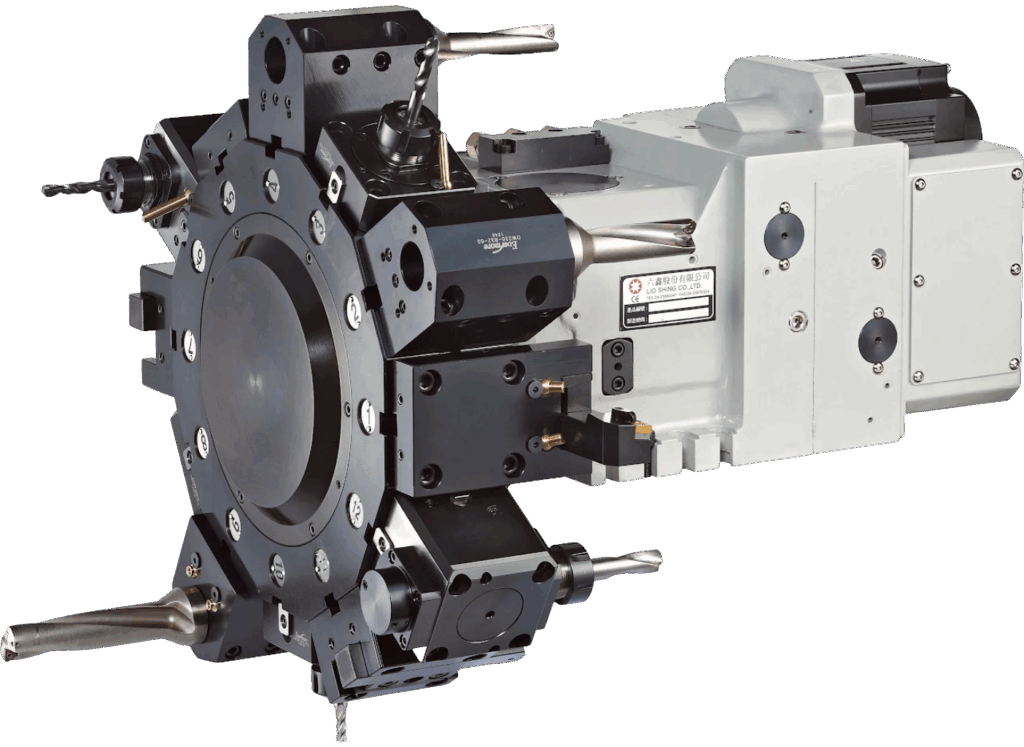
The CNC controller precisely synchronizes spindle rotation with Z-axis feed, providing accurate tapping depth and high efficiency. This is the standard tapping method for modern machining centers and AEGIS CNC Power Turret models.
Prerequisites for rigid tapping: the spindle must have high-resolution encoder feedback, and the controller must support rigid tapping mode. In FANUC systems, this is typically enabled with G84 combined with M29; command syntax varies slightly by controller (FANUC, Siemens, Mitsubishi) — consult the respective system programming manual.
Floating Tapping
A floating tapping chuck with an axial buffer spring allows the tap to freely adjust its position within a small range, compensating for spindle synchronization errors. Suitable for older equipment, drill/tap machines, or applications where spindle rigidity is insufficient.
Depth repeatability is approximately ±0.1–0.5mm (depending on chuck equipment precision). Not suitable for blind holes with strict depth requirements; fully acceptable for through-hole mass production.
Tapping Method Selection Guide
| Machining Condition | Rigid Tapping | Floating Tapping |
|---|---|---|
| CNC machining center with rigid tapping support | ✔ First Choice | — |
| Blind hole, depth tolerance within ±0.3mm | ✔ Required | — |
| Older drill/tap machine / through-hole mass production | — | ✔ Acceptable |
| Tap-breaking-prone materials (titanium alloy / thin stainless steel) | — | ✔ Buffer protection |