
Chip Wrapping in Machining:
Problems & Solutions
From the limits of three traditional countermeasures to a complete analysis of controller-level oscillation cutting technology
Chip Wrapping refers to the phenomenon where chips, due to the high toughness of the material and continuous elongation under heat, fail to break naturally and instead wrap around the workpiece or turret. Its formation involves the combined effects of material properties, cutting temperature, and tool geometry — simply put, the chips are "too soft, too tough, and won't break."
Why Chip Wrapping Is the Top Threat to Automated Production Lines
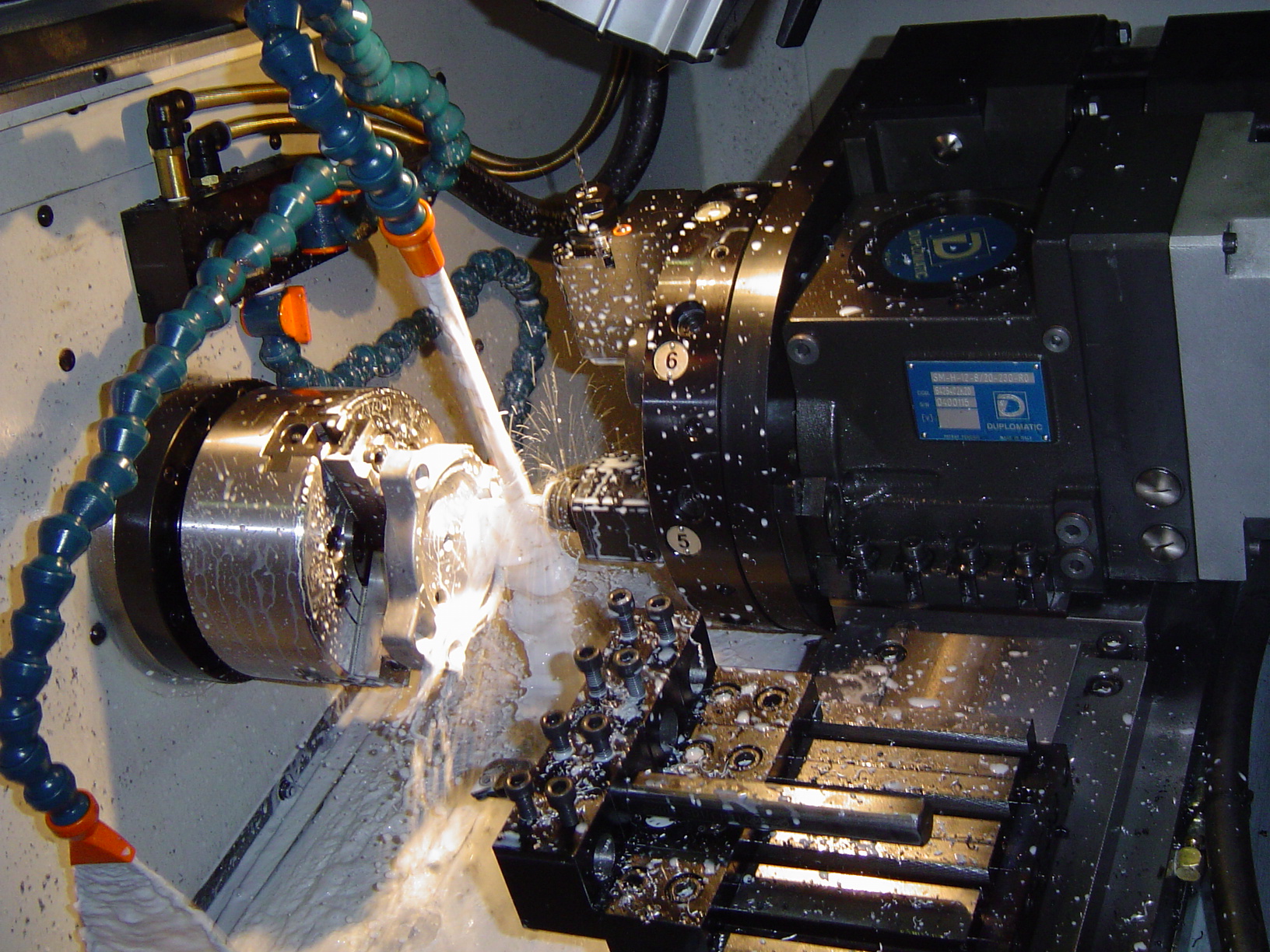
In precision metal cutting, chip wrapping has long been considered a "hidden cost" in the process. When machining ductile materials such as aluminum alloy, low-carbon steel, and stainless steel, chips tend to form as continuous helical ribbons. If they do not break naturally before leaving the cutting zone, problems quickly compound.
For the workpiece and equipment, long chips continuously accumulating on a rotating workpiece cause secondary scratches on the machined surface, degrading Ra roughness values. In severe cases, chips can pull on the insert, shortening tool life.
The impact of chip wrapping on automated production lines goes far beyond this. When machines are equipped with robot arms or gantry loaders for part handling, accumulated chips directly interfere with pick-and-place operations, trigger sensor alarms, and force line shutdowns. From a process engineering perspective, chip wrapping is not an isolated problem but a signal that cutting conditions have not entered a stable chip-breaking range — unplanned downtime from poor chip evacuation often causes greater production losses than a broken insert and is the most common practical obstacle to achieving 24-hour unmanned machining.
Technical Bottlenecks of Three Traditional Countermeasures
Engineers have long relied on three directions of adjustment to address chip wrapping, but each has limitations that are difficult to overcome.
When all three of these approaches have reached their limits —
Especially when facing high-volume continuous production with high-toughness materials, intelligent functions from the controller become the true solution path.
How Oscillation Cutting Works
Oscillation Cutting is a software function developed specifically to solve chip wrapping problems in mainstream CNC controllers. FANUC calls it "Servo Learning Oscillation"; Mitsubishi Electric calls it "Vibration Cutting." Both operate on the same principle, differing only in their algorithm implementations and applicable controller models.
Core Mechanism: This function uses deep integration between the controller and servo drive to superimpose a small near-periodic oscillation on the tool feed direction — the waveform approximates a sine wave, but is actually determined by the controller's algorithm and varies slightly by brand and settings.
Within each oscillation cycle, the effective feed creates instantaneous gaps (known in the industry as Intermittent Cutting intervals). Chips lose their continuous material support and break. Strictly speaking, the tool tip does not necessarily stop advancing completely — rather, the periodic variation in feed speed creates a breakpoint in chip thickness, forcing chips to fracture into small granular pieces.
The oscillation frequency is calculated in conjunction with spindle speed, ensuring the oscillation phase of each revolution effectively overlaps the cutting marks of the previous revolution, generating chip break points at fixed positions — which is why frequency parameters must be adjusted synchronously when spindle speed changes.
Key Advantages
For general machining, the surface impact is minimal. If used in high-precision finishing operations, oscillation may leave slight periodic texture marks; in this case, reduce the feed rate rather than disabling the function entirely.
When Purchasing a CNC Lathe: How to Confirm Oscillation Cutting Capability
Oscillation cutting is not standard equipment on all controllers; it is typically provided as an optional add-on that is not factory-enabled by default. Confirm explicitly during procurement whether it has been activated.
(Servo Learning Chip Breaking)
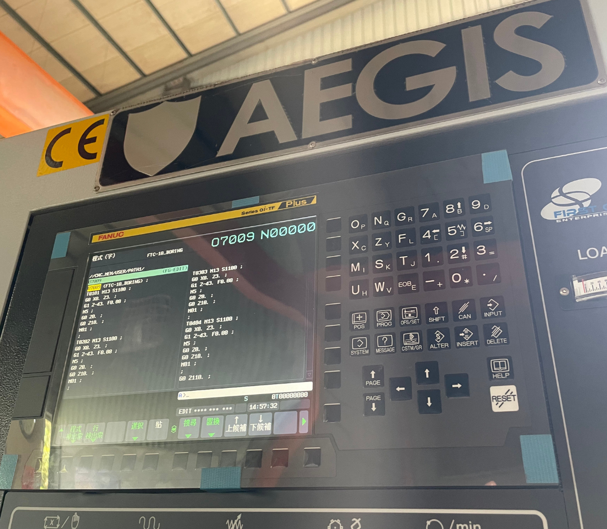
- 0i-F Plus (version 1.0 and later)
- 30i / 31i / 32i-B (STEP2 and above)
- Compatible servo card specification required
- Number of oscillatable axes depends on hardware configuration
- M800V / M80V series and above
- Recommend written confirmation at quotation stage
- Whether the function is included in the delivery configuration
Activation procedures vary by controller brand and version; consult the machine manufacturer or controller distributor to confirm specific activation conditions and purchase options.
During procurement, confirm: whether the oscillation cutting function has been purchased and activated; the number of supported oscillation axes; and whether the machine's chip evacuation system design is compatible with small chip output (e.g., chip conveyor specification).
For factories planning to implement automated production lines —
The controller's chip-breaking capability and its compatibility with robot arm integration should be treated as equally important selection criteria as spindle power.
Want to Know About AEGIS CNC Controller Specifications?
First Chant Enterprise offers both FANUC and Mitsubishi Electric controller options. Contact us to inquire about oscillation cutting support status for each machine model.