Comparison of Three Polygon Turning Methods
There are currently three mainstream methods for machining hexagonal or square cross-sections on a CNC lathe. These three approaches are not mutually exclusive substitutes — rather, each involves trade-offs in flat surface quality, cycle efficiency, and equipment requirements. Clarify your machining priorities before choosing.
| Machining Method | Technical Principle | Surface Type | Best For | Main Limitation |
|---|---|---|---|---|
| Polar Coordinate Machining C+X Axis Interpolation |
C-axis and X-axis interpolate to simulate milling path | True Geometric Flat | Prototyping, small urgent quantities | Face-by-face cutting; longest cycle time |
| Y-Axis Power Turret Milling Y-Axis Interpolation |
Y-axis drives end mill face by face | True Geometric Flat | High precision requirements, special profiles | Each face machined individually; fast tool wear |
| Polygon Turning Polygon Turning |
Spindle and attachment electronically geared; multi-edge forms all faces in one pass | Near-Flat (Micro Arc) | High-volume production; cycle efficiency priority | Requires synchronization function and polygon attachment hardware |
About "Surface Type": Milling (C-axis or Y-axis interpolation) produces a true geometric flat surface; polygon turning produces a near-flat surface composed of micro arcs — this is not a quality defect but an inherent characteristic of the machining principle. For standard fasteners (hex nuts, fittings), near-flat surfaces typically meet requirements fully; for special applications with higher flatness or mating requirements, evaluate milling solutions.
Core Principle: Synchronized Rotation of Spindle and Cutting Tool
The ability of polygon turning to machine flat surfaces while the spindle rotates continuously relies on the Electronic Gearing mechanism. The controller locks the workpiece spindle speed and polygon attachment rotation in a fixed ratio, causing the multi-edge cutter to precisely repeat its interference with the workpiece surface every revolution, forming a near-flat geometric profile.
The speed ratio (workpiece speed to tool speed) determines the number of flat faces formed. For standard symmetric polygons, the following approximate relationship applies:
This is an approximate relationship for standard symmetric polygons, provided as a setup reference.
Speed Ratio vs. Face Count Reference
| Target Faces | Number of Edges | Speed Ratio (Workpiece : Tool) | Typical Applications |
|---|---|---|---|
| 2 Faces (Flat) | 2 Edges | 1 : 1 | Wrench flats, flat-head parts |
| 4 Faces (Square) | 2 Edges | 1 : 2 | Square-head bolts, valve stems |
| 6 Faces (Hexagonal) | 2 Edges | 1 : 3 | Standard hex nuts, fittings |
| 6 Faces (Hexagonal) | 3 Edges | 1 : 2 | Higher-efficiency hex mass production |
Setup Note: The product of edge count and speed ratio should be an even number. Odd combinations create asymmetric cutting forces that cannot balance, causing the spindle to experience unilateral radial load and increased vibration, dramatically reducing both accuracy and tool life — not used in practice. Actual forming results still require verification of tool phase and engagement position.
Three Reasons to Choose Polygon Turning
Compared to Y-axis milling which requires positioning stops for each face, polygon turning's continuous cutter rotation completes all flat faces in a single sweep. In batch production conditions, hexagonal cross-section cycle time can be shortened several-fold (typically 3 to 6 times, depending on face count and material) — one of the most direct technical means of increasing production capacity on a manufacturing line.
Compared to indexing operations that require frequent C-axis positioning, locking, and acceleration/deceleration cycles, polygon turning maintains constant spindle speed, effectively reducing servo driver thermal load, minimizing cumulative electronic component wear from back-EMF, and eliminating repetitive indexing mechanism wear — contributing to longer overall machine electronic component service life.
Polygon turning does not rely on complex axis interpolation paths. The controller's computation load is low, program logic is simple, and integration into bar feeder systems or fully automated production lines is easier — making it well-suited for unmanned continuous production environments.
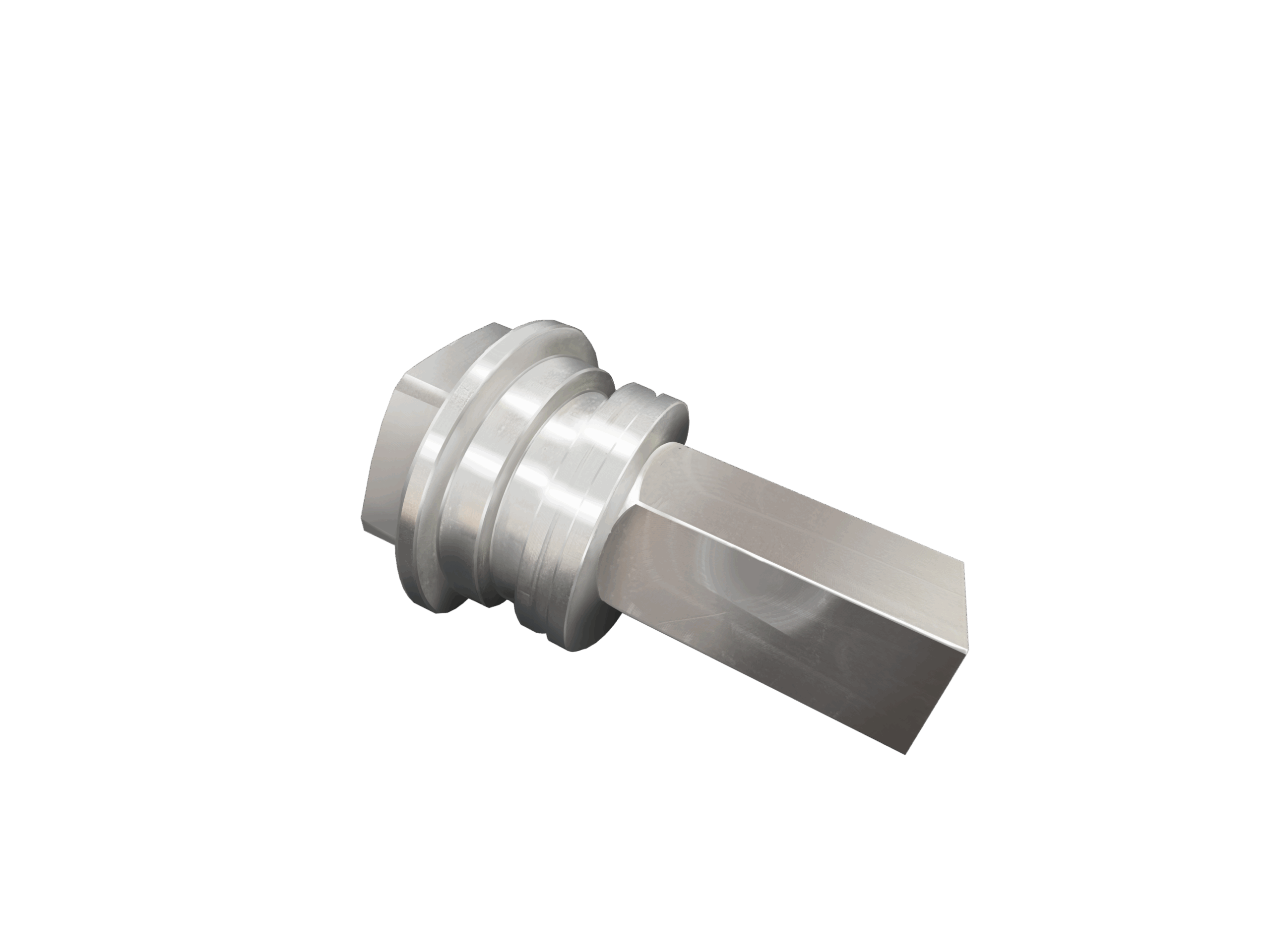
Common Application Scenarios
Machine Requirements and Usage Limitations
Polygon turning has specific hardware and software requirements that must be verified item by item before implementation.
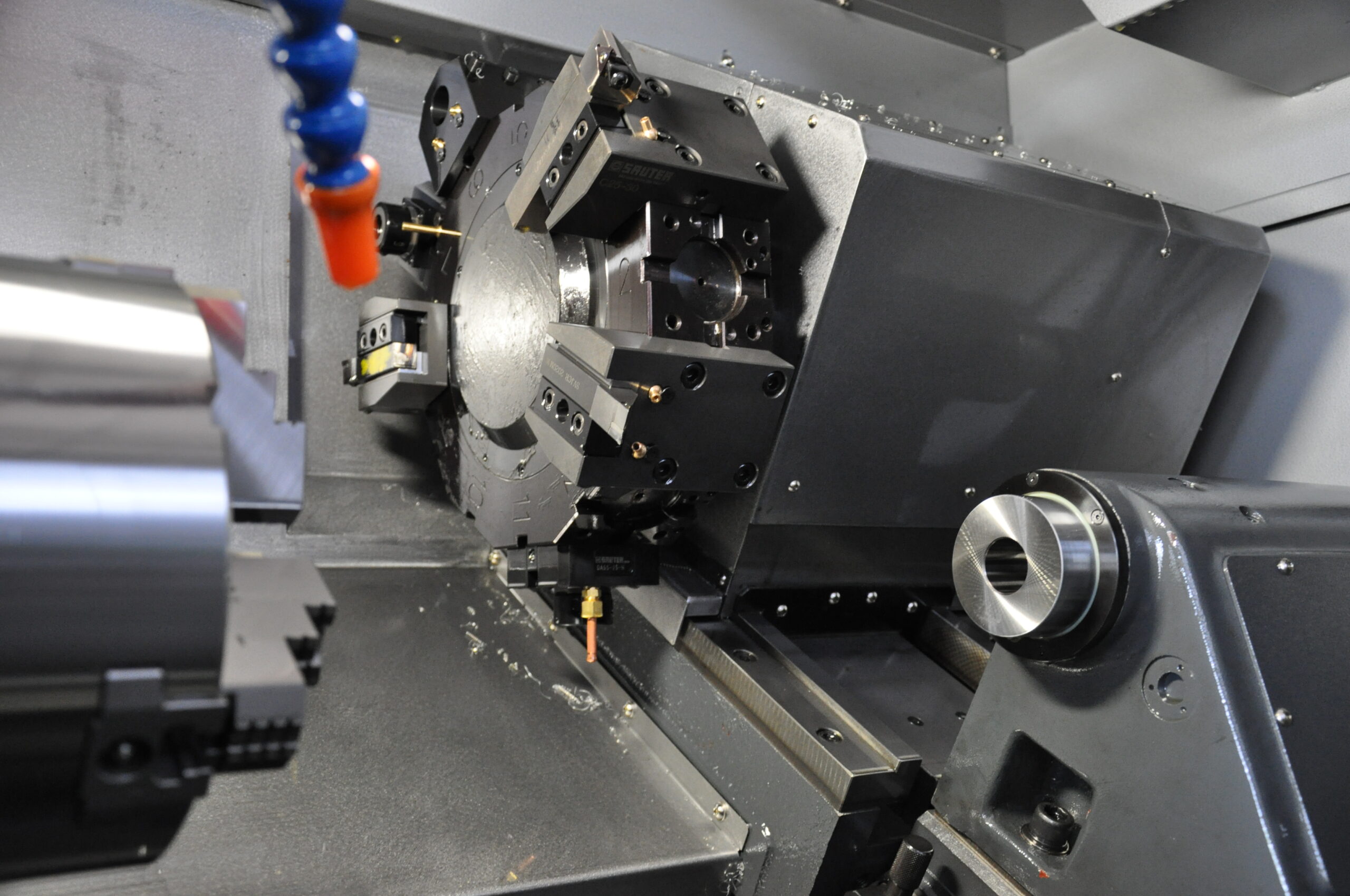
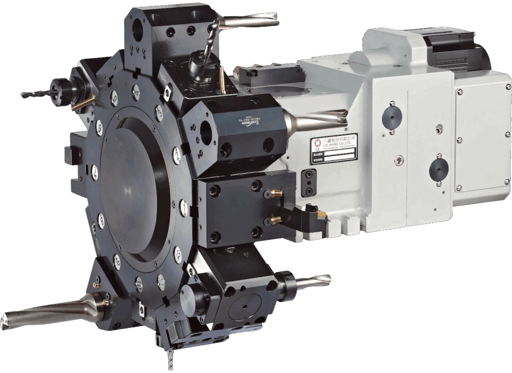
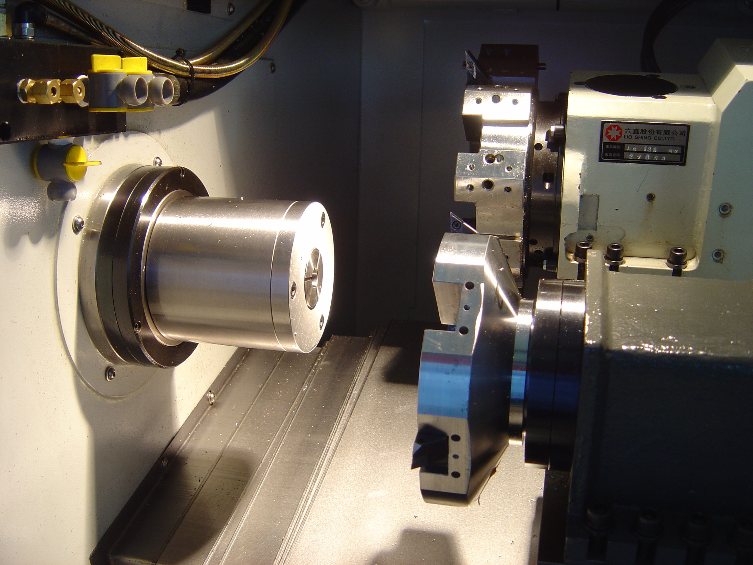
Polygon turning mechanism configuration varies by manufacturer design philosophy. The common approach is to mount a Polygon Attachment on the turret, with two drive types:
Passive Drive: The spindle drives the cutter via gears or belts; fixed speed ratio, simpler structure — an older design.
Active Drive: The attachment has its own independent motor; highly flexible speed ratio setting, better synchronization accuracy — the mainstream configuration for modern multi-tasking machines.
AEGIS CNC FTC-10PT adopts a higher-specification design — a dedicated independent Polygon Turning unit separate from the turret, with rigidity specifically optimized for the impact characteristics of polygon interrupted cutting.
⚠ Polygon turning is interrupted cutting — the cutter periodically enters and exits the workpiece, generating impact forces. Insufficient mechanism rigidity easily causes chatter marks on the flat surfaces, one of the most common symptoms encountered during on-site troubleshooting.
The controller (FANUC, Mitsubishi, and other mainstream brands) must enable the spindle synchronization function to ensure precise speed locking between the workpiece spindle and tool throughout the entire machining process.
Any speed deviation will directly cause surface distortion or tool damage — this synchronization is the core control condition that makes the entire method work. Before purchasing a machine or adding this function, confirm that the controller version supports this feature; some models require additional license activation.
Material Suitability Assessment
Polygon turning is interrupted cutting and places certain toughness demands on the workpiece material. Evaluate material characteristics before implementation:
| Material Type | Suitability | Notes |
|---|---|---|
| Free-Cutting Steel | ✔ Best Choice | First-choice material; best tool life; suitable for high-speed mass production |
| Aluminum Alloy, Brass | ✔ Suitable | High-speed cutting; ensure smooth chip evacuation to avoid built-up edge |
| Austenitic Stainless Steel (SUS304) | △ Use Caution | High adhesion risk; high-speed interrupted cutting easily causes chip spray; requires adequate coolant and chip guard |
| Martensitic Stainless Steel | △ Feasible | Faster tool wear; regularly inspect tool condition; recommend shorter tool change intervals |
| High-Hardness Alloy Steel, Hardened Steel | ✘ Not Recommended | Tool life significantly shortened under interrupted impact; requires case-by-case evaluation of tool specs and cutting parameters |