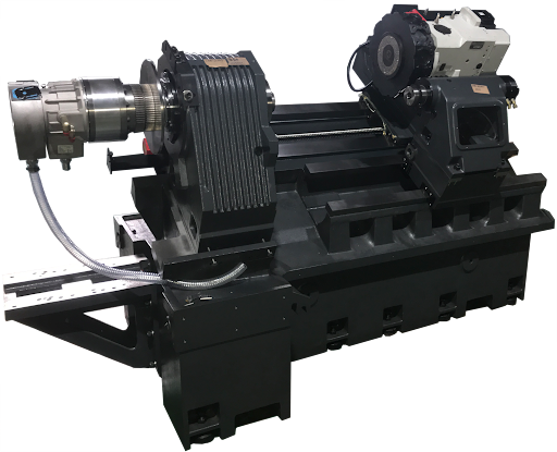
Basic Definition and Function of the Turret
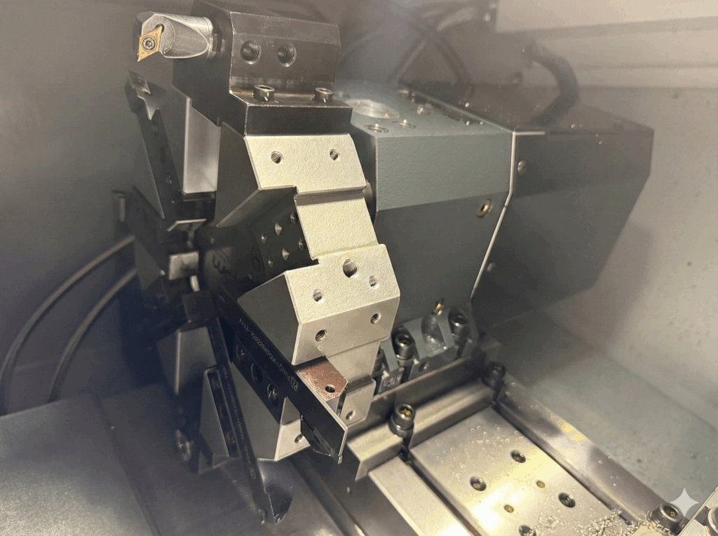
On traditional manual lathes, changing a tool could take several minutes. On a CNC lathe, the Turret carries all the required "weapons" (turning tools, drills, boring bars) at once and completes tool changes in fractions of a second under program command.
Turret Structure: Typically an 8-, 10-, 12-, or 16-sided rotating device. Each face is a "Station" that can hold different toolholders or cutting tools. Via program commands (e.g., T0101), the Turret automatically rotates to position the designated tool facing the workpiece for machining.
Station count is typically chosen based on the number of tool types required for the most complex operation. It is recommended to reserve 2–3 spare stations. Contact the AEGIS technical team to discuss detailed configurations.
Complete Analysis of Three Turret Types
Based on drive method and function, CNC lathe turrets are mainly divided into three types. Understanding their differences is the first step in selecting the right machine.
The dominant early design. Hydraulic cylinder force releases the locking mechanism (curvic coupling), a hydraulic motor or mechanical cam rotates to change tools, then hydraulic pressure re-locks the turret.
- Simple structure, strong clamping lock force, good rigidity
- Mature components, relatively easy to troubleshoot
- Slower tool change speed (typically over 1 second)
- Hydraulic oil temperature affects stability; long-term use carries oil leak risk
The current market mainstream for CNC lathes. A single servo motor directly and precisely controls the rotation angle, making tool changes fast and smooth.
- Adjacent station indexing in only 0.2–0.3 seconds; dramatically shortens non-machining time
- Precise servo positioning; typically uses "no-lift" design for smoother operation
- No complex hydraulic circuit; lower maintenance cost and failure rate
- Higher cost than hydraulic turret
Standard equipment on Turn-Mill Centers. The turret includes an internal gear or belt transmission mechanism; with live toolholders installed, the tool can rotate at high speed for milling, drilling, and more.
- Combined with C-axis or Y-axis, enables multi-tasking on workpiece side faces and end faces
- Achieves "done-in-one" machining, greatly reducing clamping count and cumulative errors
- Highest machine cost and complexity
- Live toolholders require additional purchase; higher operation and maintenance threshold
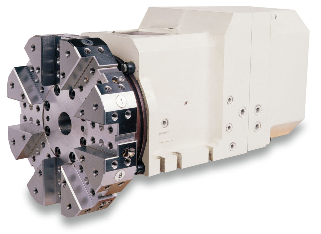
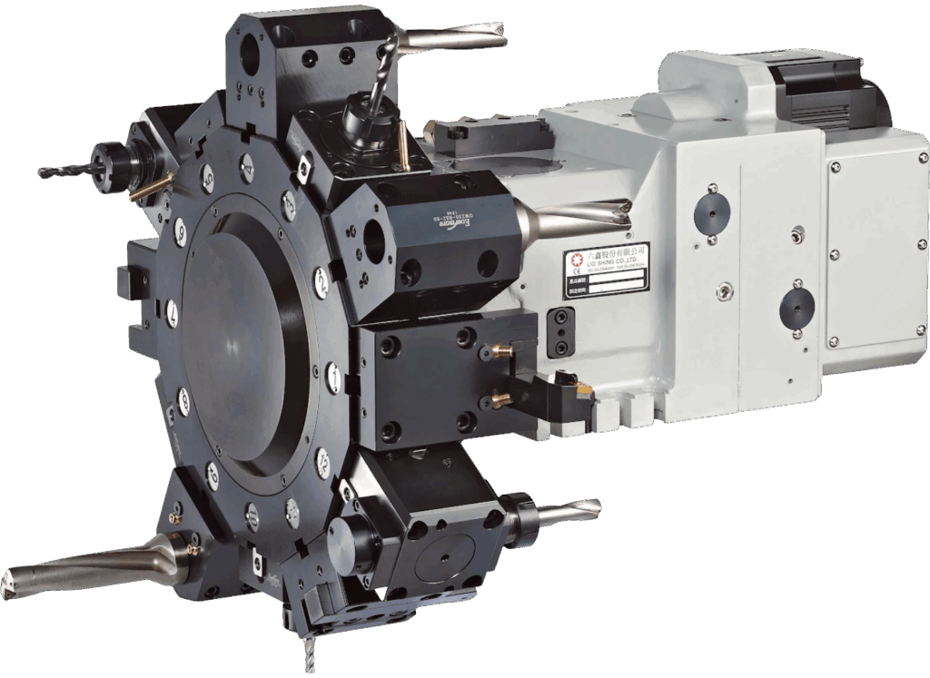
Traditional CNC lathes can only perform "rotationally symmetric" machining. With a Power Turret, the same machine can mill, drill, and tap on the workpiece's side faces or end faces, completing all operations in a single setup, eliminating positioning errors from multiple machine setups and dramatically improving accuracy and efficiency.
How to Choose the Right Turret Configuration?
Each of the three turret types has its suitable application scenarios — none is absolutely better. The following three directions will help you quickly narrow your choice:
-
1Prioritize Tool Change Speed Requirements If your parts have many machining steps and frequent non-cutting movements, the servo turret's 0.2–0.3-second change time can significantly boost production capacity. If operations are simple and speed is not critical, the lower cost of a hydraulic turret offers better economic value.
-
2Determine If Multi-Tasking Capability Is Needed If your workpieces require side drilling, tapping, or milling beyond turning, a Power Turret on a Turn-Mill Center is the only option. Done-in-one machining not only saves time but also avoids cumulative positioning errors from multiple setups.
-
3Determine Station Count Based on Tool Requirements Choose station count based on the number of tool types required for your most complex operation, and reserve 2–3 spare stations. The optimal Turret configuration varies by workpiece and production line — contact the AEGIS technical team for a one-on-one assessment.